(!)Due to Microsoft's end of support for Internet Explorer 11 on 15/06/2022, this site does not support the recommended environment.
Instead, please kindly use other browsers like Google Chrome, Microsoft Edge or Mozilla Firefox.
50,000 Stock items for Same Day Ship Out.
All Categories
Categories
- Automation Components
A wide variety of standard and configurable components for factory automation engineers in industries such as automotive, semiconductor, packaging, medical and many more.
- Linear Motion
- Rotary Motion
- Connecting Parts
- Rotary Power Transmission
- Motors
- Conveyors & Material Handling
- Locating, Positioning, Jigs & Fixtures
- Inspection
- Sensors, Switches
- Pneumatics, Hydraulics
- Vacuum Components
- Hydraulic Equipment
- Discharging / Painting Devices
- Pipe, Tubes, Hoses & Fittings
- Modules, Units
- Heaters, Temperature Control
- Framing & Support
- Casters, Leveling Mounts, Posts
- Doors, Cabinet Hardware
- Springs, Shock Absorbers
- Adjusting, Fastening, Magnets
- Antivibration, Soundproofing Materials, Safety Products
- Fasteners
A good selection of accessories such as screws, bolts, washers and nuts that you may need for your daily engineering usage.
- Materials
Browse industrial materials ranging from heat insulating plates, sponges, to metal and plastic materials in different sizes to meet your various applications.
- Wiring Components
A wide variety of wiring parts for connecting and protecting control and PC parts including Connectors, Cables, Electric Wires, Crimping Terminals and more.
- LAN Cables / Industrial Network Cables
- Cables by Application
- Cables with Connectors
- RS232 / Personal Computers / AV Cables
- Wires/Cables
- Connectors (General Purpose)
- Crimp Terminals
- Zip Ties
- Cable Glands
- Cable Bushings/Clips/Stickers
- Screws/Spacers
- Cable Accessories
- Tubes
- Protection Tubes
- Ducts/Wiremolds
- General Purpose Tools
- Dedicated Tools
- Soldering Supplies
- Electrical & Controls
A wide variety of controls and PC parts for electrical engineers including Controls, Powers, PC parts and more.
- Cutting Tools
A wide variety of cutting tools for many uses and work materials including End Mills, Drills, Cutters, Reamers, Turning Tools and more.
- Carbide End Mills
- HSS End Mills
- Milling Cutter Inserts/Holders
- Customized Straight Blade End Mills
- Dedicated Cutters
- Turning Tools
- Drill Bits
- Screw-Hole-Related Tools
- Reamers
- Chamfering / Centering Tools
- Fixtures Related to Cutting Tools
- Step Drills
- Hole Saws
- Clean Key Cutters
- Core Drills (Tip Tools)
- Magnetic Drilling Machine Cutters
- Drill Bits for Electric Drilling Machines
- Woodworking Drill Cutters
- Drills for Concrete
- Processing Tools
A wide variety of tools and supplies used in processing including Machine Tools, Measurement Tools, Grinding and Polishing Supplies and more.
- Material Handling & Storage
A wide variety of goods used in shipment, material handling and warehouse including Tape supplies, Stretch film, Truck, Shelf, Crane and more.
- Tape Supplies
- Cushioning Materials
- Stretch Films
- Cardboard
- Plastic Bags
- PP Bands
- Magic Tapes / Tying Belts
- Rubber Bands
- Strings/Ropes
- Cable Ties
- Tags
- Labelers
- Unpacking Cutters
- Packing Support Equipment
- Cloth Sheets for Packing
- Conveyance/Dolly Carts
- Tool Wagons
- Tool Cabinets / Container Racks
- Lifters / Hand Pallets
- Container Pallets
- Storage Supplies
- Shelves/Racks
- Work Benches
- Suspended Clamps/Suspended Belts
- Jack Winches
- Chain Block Cranes
- Bottles/Containers
- Bicycle Storage Area
- Safety & General Supplies
A large variety of goods for every kind of factories and offices including Protection items, Cleaning supplies, sanitations, office supplies and more.
- Lab & Clean Room Supplies
A large variety of items used in R&D and Clean Room including research Equipment, Laboratory Essentials, Analysis Supplies, Clean Environment-Related Equipment and more.
- Press Die Components
Choose from thousands of standard stamping die components including Punch & Die, Gas Springs, Guide Components, Coil Springs and many more.
- Plastic Mold Components
Browse our wide variety of mold components including Ejector Pins, Sleeves, Leader Components, Sprue Bushings and many more.
- Ejector Pins
- Sleeves, Center Pins
- Core Pins
- Sprue bushings, Gates, and other components
- Date Mark Inserts, Recycle Mark Inserts, Pins with Gas Vent
- Undercut, Plates
- Leader Components, Components for Ejector Space
- Mold Opening Controllers
- Cooling or Heating Components
- Accessories, Others
- Components of Large Mold, Die Casting
- Injection Molding Components
Browse our injection molding components including Heating Items, Couplers, Hoses and more.
- Injection Molding Machine Products
- Accessories of Equipment
- Auxiliary Equipment
- Air Nippers
- Air Cylinders
- Air Chuck for Runner
- Chuck Board Components
- Frames
- Suction Components
- Parallel Air Chuck
- Special Air Chuck
- Chemical for Injection Molding
- Mold Maintenance
- Heating Items
- Heat Insulation Sheets
- Couplers, Plugs, One-touch Joints
- Tubes, Hoses, Peripheral Components
Search by Application
Brands
- Scheduled Maintenance Notice: This site will be unavailable due to scheduled maintenance from 9:00 24/11/2024 to 7:00 (SGT) 25/11/2024. We apologize for the inconvenience.
- Notice of End of Sales for Economy Series Pneumatic Equipment Category. More information.
New Spring-Type Connector 770 (WINSTA), 2 Connections (Transition Allowed) (770-204)
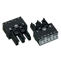
This connector allows for easy connection of single wires and stranded wires, making transition possible.
[Features]
·You can easily make connections of single wires by simply inserting them and of stranded wires with a compact screwdriver.
·No need for crimp terminals or screw tightening to reduce work time.
[Applications]
·As a power supply connector for equipment.
·Ideal for connecting a single wire of a 100-V AC power supply and a stranded wire of equipment.
·When both power supply transition and branch are required.
·Realizes labor saving for making connections at the work site.
·Nylon connector suitable for wiring facility lighting.
Part Number
Configured Part Number is shown.
770-204
Features of this product
- Available for 3-, 4- and 5-contact.
- Compatible with 0.5 to 4 sq / AWG20-12 stranded wire and single wire (ø1.6 and ø2.0 mm IV single wires acceptable).
- Rated at 205 V / 25 A, it is compact but has ample capacity.
- Reverse insertion prevention structure and retaining lock (optional) are available.
- 2 cables can be connected per position, enabling transition wiring by the connector.
Preparation of cables
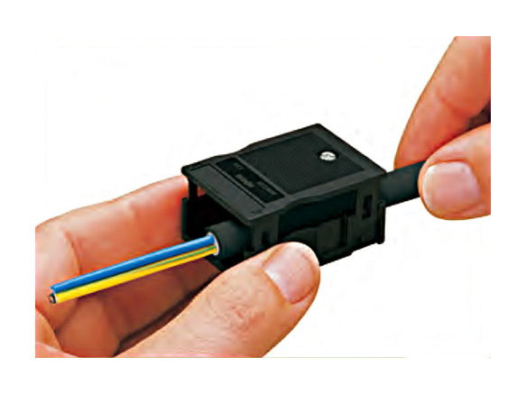
Thread the cable through the housing before connection.
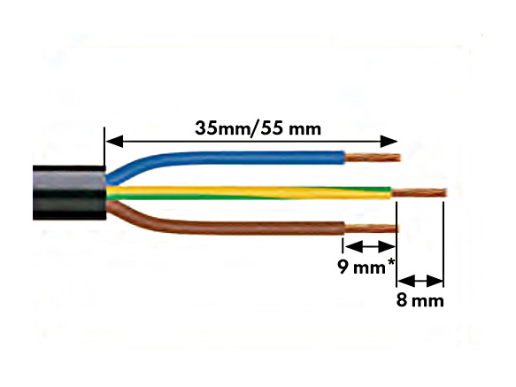
1. Stripping length of the sheath = 35 mm (2-position), 55 mm (3- to 5-position)
Caution: This is a reference value. Adjust the length depending on the type of cable.
2. Stripping length of the conductor = 9 mm *
* 13 mm for ø3.4 to ø4.1 mm in cable coating outer diameter
3. Length of the ground wire extension = 8 mm
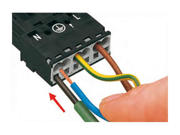
Connect the cable to the connector with the cable run through the housing. (See below for how to make connections)
Connection Method: Push-in CAGE CLAMP
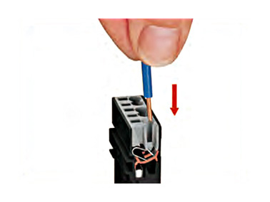
Connection for a single wire: You can make connections by simply inserting a single wire by stripping out the coating.
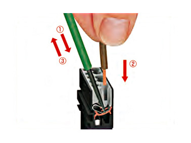
Connection for a stranded wire: (1) Release the spring with a dedicated screwdriver (blade width 2.5 mm), and (2) insert the stripped cable as far as it goes.
(3) Connection is completed by removing the screwdriver.

Removal: (1) Release the spring with a dedicated screwdriver (blade width 2.5 mm), and (2) remove the cable.
Attaching a strain relief housing

Put the connector in which connections of the wires were made in the strain relief housing so that the TOP surface matches.

Press the cover from the top and bottom until the mating clip snaps.
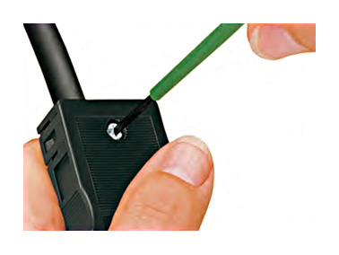
Tighten the fixing screw to secure the cable to the housing.
Coding
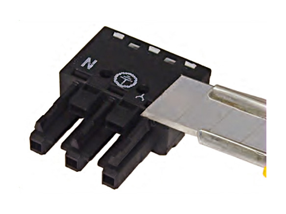
Cut out the overmolding pin that into the socket with a cutter or the like.
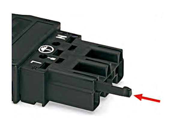
Inserting the folded pin into the plug prevents incorrect insertion upon the use of a connector with the same number of positions.
Marking
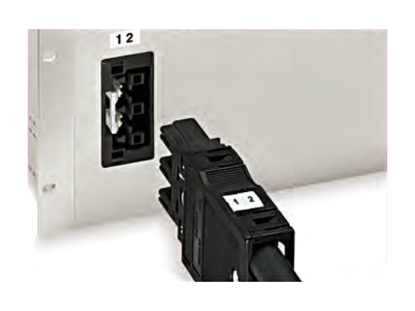
WSB marking system: an example of marking on the strain relief housing.
Locking lever
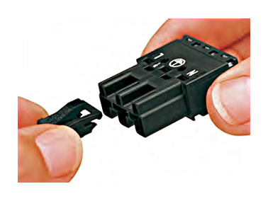
Pay attention to the attaching direction.
Snap-in attachment of the locking lever (optional), with removal prevention allowed by locking the connector.

Operation of a finger-operated type locking lever
1. Push down the locking lever.
2. Pull the connector to separate.

Operation of a tool-operated locking lever
1. Insert a screwdriver at the bottom of the locking lever.
2. Pull the connector to separate.
Instructions to attach a panel penetration type
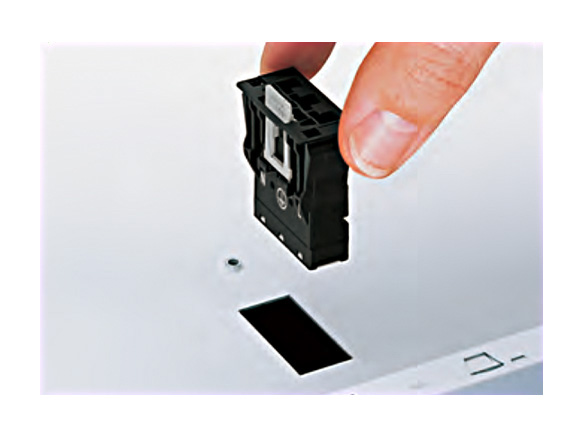
How to attach a penetration type connector: It can be attached simply by making a square cut hole in the panel and fitting it in.

How to remove a penetration-type connector: The connector can be removed by pressing the locks on its both sides and push it forward from the back of the panel.
Cover plate
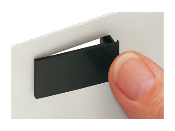
A cover plate is also available when the cut hole is not used.
Development story
The WAGO Corporation is a global enterprise from Germany that has a track record of more than 50 years as a pioneer in spring type terminal blocks.
The WINSTA connector is an epoch-making product developed to save labor in the conventional connector processing work using crimping pins and solder.
This eliminates the need for dedicated pins or expensive crimp tools, shortening the working time and reducing the total cost.
It can be widely used for cable connection in all fields, including various industrial equipment and general applications.
| Part Number |
|---|
| 770-204 |
| Part Number | Standard Unit Price | Minimum order quantity | Volume Discount | Days to Ship | RoHS | V/W/X | Applicable pin/contact | Number of Pins | Allowable Voltage (V) | Pin pitch (mm) | Conforming Wire | Flexible stranded wire Conforming cross-sectional area (mm2) | Cross-sectional area matching with strand wire (mm2) | Maximum Outer Diameter of Coat (mm) | Insulation materials | Flame-Retardant Grade | Contact materials | Note |
|---|---|---|---|---|---|---|---|---|---|---|---|---|---|---|---|---|---|---|
SGD 7.64 | 1 Piece(s) | 4 Day(s) or more | 10 | [Other] WINSTA MIDI | Female (socket) | 4 | 400 | - | Single wire / flexible stranded wire / stranded wire | 0.5 to 4 | 0.5–2.5 | 4.1 | - | - | - | 2 wires can be connected to 1 core (pole) |
Loading...
Basic Information
| Connector Shape | Square shape | Connector series initials | V/W/X | Application | Cable Connection |
|---|---|---|---|---|---|
| Allowable Current(A) | 25 | Wire connection method | Screwless | Connection direction | Straight |
| Representative Standard | UL / CUL / CSA | Product Type | No housing | Color | Black |
| Single wire conforming cross-section(mm2) | 0.5 to 4 | Wire conforming size(AWG) | 20 to 12 |
Please check the type/dimensions/specifications of the part 770-204 in the New Spring-Type Connector 770 (WINSTA), 2 Connections (Transition Allowed) series.
Specification/Dimensions
-
Pin pitch(mm)
- 10
-
Conforming Wire
-
Insulation materials
- Nylon 6.6
-
Flame-Retardant Grade
- V0
-
Contact materials
- Copper or copper alloy
-
V/W/X
- Other
- Other
-
Applicable pin/contact
- Male (plug)
- Female (socket)
-
Number of Pins
-
Allowable Voltage(V)
-
Flexible stranded wire Conforming cross-sectional area(mm2)
- 0.5 to 4
-
Cross-sectional area matching with strand wire(mm2)
- 0.5–2.5
-
Maximum Outer Diameter of Coat(mm)
- 4.1
Days to Ship
-
- All
- 4 Day(s) or Less
Specify Alterations
- The specifications and dimensions of some parts may not be fully covered. For exact details, refer to manufacturer catalogs .
Similar Part Numbers
| Part Number |
|---|
| 770-202 |
| 770-203 |
| 770-205 |
| 770-212 |
| 770-213 |
| 770-214 |
| Part Number | Standard Unit Price | Minimum order quantity | Volume Discount | Days to Ship | RoHS | V/W/X | Applicable pin/contact | Number of Pins | Allowable Voltage (V) | Pin pitch (mm) | Conforming Wire | Flexible stranded wire Conforming cross-sectional area (mm2) | Cross-sectional area matching with strand wire (mm2) | Maximum Outer Diameter of Coat (mm) | Insulation materials | Flame-Retardant Grade | Contact materials | Note |
|---|---|---|---|---|---|---|---|---|---|---|---|---|---|---|---|---|---|---|
SGD 4.57 | 1 Piece(s) | 4 Day(s) or more | 10 | [Other] WINSTA® MIDI | Female (socket) | - | - | 10 | - | - | - | - | Nylon 6.6 | V0 | Copper or copper alloy | - | ||
SGD 5.64 | 1 Piece(s) | 4 Day(s) or more | 10 | [Other] WINSTA MIDI | Female (socket) | 3 | 250 | - | flexible stranded wire / Single wire / stranded wire | 0.5 to 4 | 0.5–2.5 | 4.1 | - | - | - | 2 wires can be connected to 1 core (pole) | ||
SGD 9.47 | 1 Piece(s) | 4 Day(s) or more | 10 | [Other] WINSTA MIDI | Female (socket) | 5 | 400 | - | flexible stranded wire / Single wire / stranded wire | 0.5 to 4 | 0.5–2.5 | 4.1 | - | - | - | 2 wires can be connected to 1 core (pole) | ||
SGD 4.07 | 1 Piece(s) | 4 Day(s) or more | 10 | [Other] WINSTA® MIDI | Male (plug) | - | - | 10 | - | - | - | - | Nylon 6.6 | V0 | Copper or copper alloy | - | ||
SGD 5.08 | 1 Piece(s) | 4 Day(s) or more | 10 | [Other] WINSTA MIDI | Male (plug) | 3 | 250 | - | flexible stranded wire / Single wire / stranded wire | 0.5 to 4 | 0.5–2.5 | 4.1 | - | - | - | 2 wires can be connected to 1 core (pole) | ||
SGD 6.10 | 1 Piece(s) | 4 Day(s) or more | 10 | [Other] WINSTA MIDI | Male (plug) | 4 | 400 | - | flexible stranded wire / Single wire / stranded wire | 0.5 to 4 | 0.5–2.5 | 4.1 | - | - | - | 2 wires can be connected to 1 core (pole) |
Tech Support
- Factory Automation, Electronics, Tools, & MRO (Maintenance, Repair and Operations)
- Tel:(65) 6733 7211 / FAX:(65) 6733 0211
- 9:00am - 6:00pm (Monday - Friday)
- Technical Inquiry


How can we improve?
How can we improve?