(!)Due to Microsoft's end of support for Internet Explorer 11 on 15/06/2022, this site does not support the recommended environment.
Instead, please kindly use other browsers like Google Chrome, Microsoft Edge or Mozilla Firefox.
50,000 Stock items for Same Day Ship Out.
All Categories
Categories
- Automation Components
A wide variety of standard and configurable components for factory automation engineers in industries such as automotive, semiconductor, packaging, medical and many more.
- Linear Motion
- Rotary Motion
- Connecting Parts
- Rotary Power Transmission
- Motors
- Conveyors & Material Handling
- Locating, Positioning, Jigs & Fixtures
- Inspection
- Sensors, Switches
- Pneumatics, Hydraulics
- Vacuum Components
- Hydraulic Equipment
- Discharging / Painting Devices
- Pipe, Tubes, Hoses & Fittings
- Modules, Units
- Heaters, Temperature Control
- Framing & Support
- Casters, Leveling Mounts, Posts
- Doors, Cabinet Hardware
- Springs, Shock Absorbers
- Adjusting, Fastening, Magnets
- Antivibration, Soundproofing Materials, Safety Products
- Fasteners
A good selection of accessories such as screws, bolts, washers and nuts that you may need for your daily engineering usage.
- Materials
Browse industrial materials ranging from heat insulating plates, sponges, to metal and plastic materials in different sizes to meet your various applications.
- Wiring Components
A wide variety of wiring parts for connecting and protecting control and PC parts including Connectors, Cables, Electric Wires, Crimping Terminals and more.
- LAN Cables / Industrial Network Cables
- Cables by Application
- Cables with Connectors
- RS232 / Personal Computers / AV Cables
- Wires/Cables
- Connectors (General Purpose)
- Crimp Terminals
- Zip Ties
- Cable Glands
- Cable Bushings/Clips/Stickers
- Screws/Spacers
- Cable Accessories
- Tubes
- Protection Tubes
- Ducts/Wiremolds
- General Purpose Tools
- Dedicated Tools
- Soldering Supplies
- Electrical & Controls
A wide variety of controls and PC parts for electrical engineers including Controls, Powers, PC parts and more.
- Cutting Tools
A wide variety of cutting tools for many uses and work materials including End Mills, Drills, Cutters, Reamers, Turning Tools and more.
- Carbide End Mills
- HSS End Mills
- Milling Cutter Inserts/Holders
- Customized Straight Blade End Mills
- Dedicated Cutters
- Turning Tools
- Drill Bits
- Screw-Hole-Related Tools
- Reamers
- Chamfering / Centering Tools
- Fixtures Related to Cutting Tools
- Step Drills
- Hole Saws
- Clean Key Cutters
- Core Drills (Tip Tools)
- Magnetic Drilling Machine Cutters
- Drill Bits for Electric Drilling Machines
- Woodworking Drill Cutters
- Drills for Concrete
- Processing Tools
A wide variety of tools and supplies used in processing including Machine Tools, Measurement Tools, Grinding and Polishing Supplies and more.
- Material Handling & Storage
A wide variety of goods used in shipment, material handling and warehouse including Tape supplies, Stretch film, Truck, Shelf, Crane and more.
- Tape Supplies
- Cushioning Materials
- Stretch Films
- Cardboard
- Plastic Bags
- PP Bands
- Magic Tapes / Tying Belts
- Rubber Bands
- Strings/Ropes
- Cable Ties
- Tags
- Labelers
- Unpacking Cutters
- Packing Support Equipment
- Cloth Sheets for Packing
- Conveyance/Dolly Carts
- Tool Wagons
- Tool Cabinets / Container Racks
- Lifters / Hand Pallets
- Container Pallets
- Storage Supplies
- Shelves/Racks
- Work Benches
- Suspended Clamps/Suspended Belts
- Jack Winches
- Chain Block Cranes
- Bottles/Containers
- Bicycle Storage Area
- Safety & General Supplies
A large variety of goods for every kind of factories and offices including Protection items, Cleaning supplies, sanitations, office supplies and more.
- Lab & Clean Room Supplies
A large variety of items used in R&D and Clean Room including research Equipment, Laboratory Essentials, Analysis Supplies, Clean Environment-Related Equipment and more.
- Press Die Components
Choose from thousands of standard stamping die components including Punch & Die, Gas Springs, Guide Components, Coil Springs and many more.
- Plastic Mold Components
Browse our wide variety of mold components including Ejector Pins, Sleeves, Leader Components, Sprue Bushings and many more.
- Ejector Pins
- Sleeves, Center Pins
- Core Pins
- Sprue bushings, Gates, and other components
- Date Mark Inserts, Recycle Mark Inserts, Pins with Gas Vent
- Undercut, Plates
- Leader Components, Components for Ejector Space
- Mold Opening Controllers
- Cooling or Heating Components
- Accessories, Others
- Components of Large Mold, Die Casting
- Injection Molding Components
Browse our injection molding components including Heating Items, Couplers, Hoses and more.
- Injection Molding Machine Products
- Accessories of Equipment
- Auxiliary Equipment
- Air Nippers
- Air Cylinders
- Air Chuck for Runner
- Chuck Board Components
- Frames
- Suction Components
- Parallel Air Chuck
- Special Air Chuck
- Chemical for Injection Molding
- Mold Maintenance
- Heating Items
- Heat Insulation Sheets
- Couplers, Plugs, One-touch Joints
- Tubes, Hoses, Peripheral Components
Search by Application
Brands
- Notice of End of Sales for Economy Series Pneumatic Equipment Category. More information.
CQSKW Series Non-Rotating Rod Type, Double Acting, Double Rod (CDQSKWB25-40DM-M9BVL)

Compact cylinder that is ideal for machine designs with small space requirements.
[Features]
· The compact auto switch (M9) will not protrude from the switch mounting groove.
· Even when auto switches are used, they do not take up extra space.
· The cross-section of the cylinder tube is the same configuration with or without an auto switch.
· Square body shape that gives you flexibility for designing machines.
· Auto switch mounting direction allows for flexible design requirements.
· 2-way basic cylinder mounting.
· Non-rotating rod with high non-rotating accuracy.
(i)Caution
- ■ SMC Product Line
Webpages for products currently without individual pages on this site will be released on an ad-hoc basis. - Refer to the manufacturer's catalog for specification and material details.
- Product images may be representative images. Refer to the manufacturer's catalog for shape details.
Part Number
Configured Part Number is shown.
CDQSKWB25-40DM-M9BVL
CQSKW Series Non-Rotating Rod Type: Double Acting, Double Rod Specifications
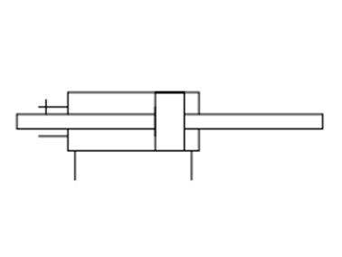
CQSKW Series symbol (without cushion)
| Tube Inner Diameter (mm) | 12 | 16 | 20 | 25 |
|---|---|---|---|---|
| Action | Double acting, double rod | |||
| Fluid | Air | |||
| Lubrication | Not required (non-lubricated) | |||
| Proof Pressure | 1.5 MPa | |||
| Maximum operating pressure | 1.0 MPa | |||
| Minimum operating pressure | 0.07 MPa | 0.05 MPa | ||
| Ambient and fluid temperature | Without auto switch: -10°C to +70 ℃ (no freezing) | |||
| With auto switch: -10°C to +60℃ (no freezing) | ||||
| Cushioning | None | |||
| Rod-end thread | Female thread | |||
| Stroke Length Tolerance | 0 to +1.0 mm | |||
| Piston Speed | 50 to 500 mm/s | |||
| Allowable kinetic energy J | 0.022 | 0.038 | 0.055 | 0.09 |
| Rod non-rotating accuracy | ±1 ° | ±0.7 ° | ||
Theoretical Output Table
(Unit: N)
| Tube inner diameter (mm) | Rod width across flats (mm) | Piston Area (mm2) | Operating Pressure (MPa) | ||
|---|---|---|---|---|---|
| 0.3 | 0.5 | 0.7 | |||
| 12 | 5.2 | 90 | 27 | 45 | 63 |
| 16 | 6.2 | 168 | 50 | 84 | 117 |
| 20 | 8.2 | 256 | 77 | 128 | 179 |
| 25 | 10.2 | 401 | 120 | 200 | 281 |
Diagram
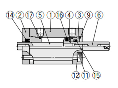
Diagram: standard, ø12 (12‑mm bore size)
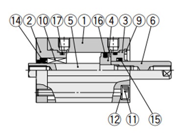
Diagram: standard, ø16 (16‑mm bore size) / ø20 (20‑mm bore size) / ø25 (25‑mm bore size)
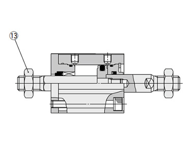
Diagram: rod end male thread
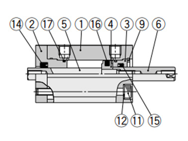
Diagram: with auto switch and built-in magnet, ø12 (12-mm bore size)
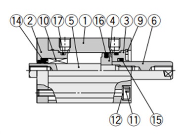
Diagram: with auto switch and built-in magnet, ø16 (16-mm bore size)
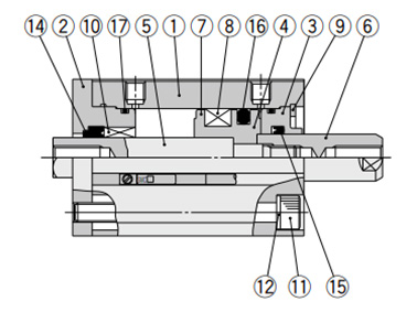
Diagram: with auto switch and built-in magnet, ø20 (20‑mm bore size) / ø25 (25‑mm bore size)
| Number | Part Name | Material | Notes |
|---|---|---|---|
| 1 | Cylinder Tube | Aluminum alloy | Hard anodized aluminum |
| 2 | Rod cover | Aluminum alloy | Anodized aluminum |
| 3 | Collar | Aluminum alloy | Anodized aluminum |
| 4 | Piston | Aluminum alloy | - |
| 5 | Piston rod A | Stainless steel | - |
| 6 | Piston rod B | Stainless steel | - |
| 7 | Spacer for Switch Type | Aluminum alloy | Chromate |
| 8 | Magnet | - | - |
| 9 | Retaining Ring | Carbon tool steel | Phosphate coated |
| 10 | Non-Rotating Guide | Oil-impregnated sintered alloy | ø16 (16‑mm bore size), ø20 (20‑mm bore size), ø25 (25‑mm bore size) |
| 11 | Hex Socket Head Cap Screw | Alloy steel | Nickel plated |
| 12 | Flat Washer | Rolled steel | Nickel plated |
| 13 | Rod end nut | Carbon steel | Zinc chromate |
| 14 | Rod seal for non-rotating | NBR | - |
| 15 | Rod packing | NBR | - |
| 16 | Piston packing | NBR | - |
| 17 | Tube gasket | NBR | - |
Drawing: ø12 to 25 (12‑mm to 25‑mm Bore Size)
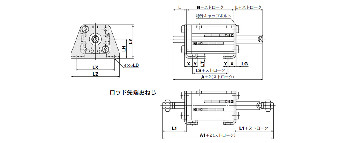
Dimensional drawings: foot type; CQSKWL, CDQSKWL
(Units: mm)
| Tube inner diameter (mm) | Stroke range (mm) | Without auto switch | With auto switch | L | L1 | LD | LG | LH | LT | LX | LY | LZ | X | Y | ||||||
|---|---|---|---|---|---|---|---|---|---|---|---|---|---|---|---|---|---|---|---|---|
| A | A1 | B | LS | A | A1 | B | LS | |||||||||||||
| 12 | 5 to 30 | 54 | 75 | 27 | 15 | 59 | 80 | 32 | 20 | 13.5 | 24 | 4.5 | 2.8 | 17 | 2 | 34 | 29.5 | 44 | 8 | 4.5 |
| 16 | 5 to 30 | 54 | 78 | 27 | 15 | 59 | 83 | 32 | 20 | 13.5 | 25.5 | 4.5 | 2.8 | 19 | 2 | 38 | 33.5 | 48 | 8 | 5 |
| 20 | 5 to 50 | 60 | 88 | 31 | 19 | 70 | 98 | 41 | 29 | 14.5 | 28.5 | 6.6 | 4 | 24 | 3.2 | 48 | 42 | 62 | 9.2 | 5.8 |
| 25 | 5 to 50 | 64 | 99 | 34 | 19 | 74 | 109 | 44 | 29 | 15 | 32.5 | 6.6 | 4 | 26 | 3.2 | 52 | 46 | 66 | 10.7 | 5.8 |
- Foot bracket material: carbon steel
- Surface treatment: nickel plated
Precautions
Usage Precautions
Warning
*Do not apply reverse torque to the piston rods sticking out from both sides of this cylinder at the same time. Torque makes connection threads inside loosen, which may cause an accident or malfunction.
In addition, install or remove the load with the 2 flats of the piston rod fixed on the load mounting side. At this time, be careful not to apply torque to the non-rotating guide. Do not fix the other side of the 2 flats of the piston rod and then apply reverse torque.
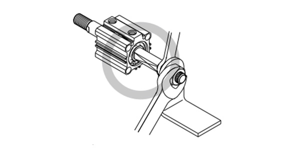
Example of correct usage of cylinder
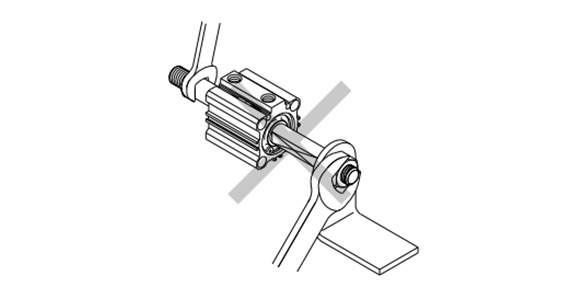
Example of incorrect use of cylinder
Caution
- *1Avoid applying rotational torque to the piston rod. The non-rotating guide may become deformed, compromising the accuracy. See below for the rotational torque allowance.
- *2The load on the piston rod must always be in an axial direction.
- ø12 (12‑mm bore size): 0.04 N·m or less
- ø16 (16‑mm bore size): 0.04 N·m or less
- ø20 (20‑mm bore size): 0.2 N·m or less
- ø25 (25‑mm bore size): 0.25 N·m or less
Installation and Removal of Retaining Rings
Caution
- *1For installation and removal, use an appropriate pair of pliers (tool for installing a type C-type retaining ring).
- *2Even when using an appropriate pair of pliers (tool for installing a type C retaining ring), proceed with caution as there is a danger of the retaining ring flying off the end of the pliers (tool) and causing bodily injury or damage to nearby equipment. After installation, make sure that the retaining ring is securely seated into the retaining ring groove before supplying air.
*See the manufacturer's catalog for product information other than that detailed above.
| Part Number |
|---|
| CDQSKWB25-40DM-M9BVL |
| Part Number | Standard Unit Price | Minimum order quantity | Volume Discount | Days to Ship | Cylinder (Tube) Inner Diameter (Ø) | Stroke (mm) | Operating Temperature (°C) | Operating Pressure (MPa) | Body Options | Auto Switches | Lead Wire | The number of the switches | Type of Mount Support |
|---|---|---|---|---|---|---|---|---|---|---|---|---|---|
- | 1 Piece(s) | Quote | 25 | 40 | -10~60 | 0.05~1 | Male rod end | M9BV | 3 | 2 pcs. | Through-Hole / Both Ends Tapped Common (Standard) |
Loading...
Basic Information
| Cylinder Operation Method | Double Acting | Rod Operation Method | Double rod | Main Body Shape | Plate Cylinder |
|---|---|---|---|---|---|
| Additional Function | With rod detent function | Environment, Applications | Standard | End Locking | No |
| Valves | No |
Please check the type/dimensions/specifications of the part CDQSKWB25-40DM-M9BVL in the CQSKW Series Non-Rotating Rod Type, Double Acting, Double Rod series.
Specification/Dimensions
-
type
- CDQSKWB□
- CDQSKWF□
- CDQSKWLC□
- CDQSKWL□
- CQSKWB□
- CQSKWF□
- CQSKWLC□
- CQSKWL□
-
Cylinder (Tube) Inner Diameter(Ø)
-
Stroke(mm)
-
Body Options
-
Auto Switches
-
Lead Wire
- 0.5
- 1
- 3
- 5
- None
-
The number of the switches
-
Type of Mount Support
- Compact foot type
- Flange type
- Foot
- Through-Hole / Both Ends Tapped Common (Standard)
-
CAD
- 2D
- 3D
Days to Ship
-
- All
- 32 Day(s) or Less
Specify Alterations
- The specifications and dimensions of some parts may not be fully covered. For exact details, refer to manufacturer catalogs .
Similar Part Numbers
| Part Number |
|---|
| CDQSKWB12-10D-M9BV |
| CDQSKWB12-10D-M9BVL |
| CDQSKWB12-10D-M9BWV |
| CDQSKWB25-45DM |
| CDQSKWB25-45DM-M9B |
| CDQSKWB25-45DM-M9BVL |
| Part Number | Standard Unit Price | Minimum order quantity | Volume Discount | Days to Ship | Cylinder (Tube) Inner Diameter (Ø) | Stroke (mm) | Operating Temperature (°C) | Operating Pressure (MPa) | Body Options | Auto Switches | Lead Wire | The number of the switches | Type of Mount Support |
|---|---|---|---|---|---|---|---|---|---|---|---|---|---|
- | 1 Piece(s) | Quote | 12 | 10 | -10~60 | 0.07~1 | Standard (rod-end female thread) | M9BV | 0.5 | 2 pcs. | Through-Hole / Both Ends Tapped Common (Standard) | ||
- | 1 Piece(s) | Quote | 12 | 10 | -10~60 | 0.07~1 | Standard (rod-end female thread) | M9BV | 3 | 2 pcs. | Through-Hole / Both Ends Tapped Common (Standard) | ||
- | 1 Piece(s) | Quote | 12 | 10 | -10~60 | 0.07~1 | Standard (rod-end female thread) | M9BWV | 0.5 | 2 pcs. | Through-Hole / Both Ends Tapped Common (Standard) | ||
- | 1 Piece(s) | Quote | 25 | 45 | -10~70 | 0.05~1 | Male rod end | Without auto switch (built-in magnet) | None | None | Through-Hole / Both Ends Tapped Common (Standard) | ||
- | 1 Piece(s) | Quote | 25 | 45 | -10~60 | 0.05~1 | Male rod end | M9B | 0.5 | 2 pcs. | Through-Hole / Both Ends Tapped Common (Standard) | ||
- | 1 Piece(s) | Quote | 25 | 45 | -10~60 | 0.05~1 | Male rod end | M9BV | 3 | 2 pcs. | Through-Hole / Both Ends Tapped Common (Standard) |


How can we improve?
How can we improve?