(!)Due to Microsoft's end of support for Internet Explorer 11 on 15/06/2022, this site does not support the recommended environment.
Instead, please kindly use other browsers like Google Chrome, Microsoft Edge or Mozilla Firefox.
50,000 Stock items for Same Day Ship Out.
All Categories
Categories
- Automation Components
A wide variety of standard and configurable components for factory automation engineers in industries such as automotive, semiconductor, packaging, medical and many more.
- Linear Motion
- Rotary Motion
- Connecting Parts
- Rotary Power Transmission
- Motors
- Conveyors & Material Handling
- Locating, Positioning, Jigs & Fixtures
- Inspection
- Sensors, Switches
- Pneumatics, Hydraulics
- Vacuum Components
- Hydraulic Equipment
- Discharging / Painting Devices
- Pipe, Tubes, Hoses & Fittings
- Modules, Units
- Heaters, Temperature Control
- Framing & Support
- Casters, Leveling Mounts, Posts
- Doors, Cabinet Hardware
- Springs, Shock Absorbers
- Adjusting, Fastening, Magnets
- Antivibration, Soundproofing Materials, Safety Products
- Fasteners
A good selection of accessories such as screws, bolts, washers and nuts that you may need for your daily engineering usage.
- Materials
Browse industrial materials ranging from heat insulating plates, sponges, to metal and plastic materials in different sizes to meet your various applications.
- Wiring Components
A wide variety of wiring parts for connecting and protecting control and PC parts including Connectors, Cables, Electric Wires, Crimping Terminals and more.
- LAN Cables / Industrial Network Cables
- Cables by Application
- Cables with Connectors
- RS232 / Personal Computers / AV Cables
- Wires/Cables
- Connectors (General Purpose)
- Crimp Terminals
- Zip Ties
- Cable Glands
- Cable Bushings/Clips/Stickers
- Screws/Spacers
- Cable Accessories
- Tubes
- Protection Tubes
- Ducts/Wiremolds
- General Purpose Tools
- Dedicated Tools
- Soldering Supplies
- Electrical & Controls
A wide variety of controls and PC parts for electrical engineers including Controls, Powers, PC parts and more.
- Cutting Tools
A wide variety of cutting tools for many uses and work materials including End Mills, Drills, Cutters, Reamers, Turning Tools and more.
- Carbide End Mills
- HSS End Mills
- Milling Cutter Inserts/Holders
- Customized Straight Blade End Mills
- Dedicated Cutters
- Turning Tools
- Drill Bits
- Screw-Hole-Related Tools
- Reamers
- Chamfering / Centering Tools
- Fixtures Related to Cutting Tools
- Step Drills
- Hole Saws
- Clean Key Cutters
- Core Drills (Tip Tools)
- Magnetic Drilling Machine Cutters
- Drill Bits for Electric Drilling Machines
- Woodworking Drill Cutters
- Drills for Concrete
- Processing Tools
A wide variety of tools and supplies used in processing including Machine Tools, Measurement Tools, Grinding and Polishing Supplies and more.
- Material Handling & Storage
A wide variety of goods used in shipment, material handling and warehouse including Tape supplies, Stretch film, Truck, Shelf, Crane and more.
- Tape Supplies
- Cushioning Materials
- Stretch Films
- Cardboard
- Plastic Bags
- PP Bands
- Magic Tapes / Tying Belts
- Rubber Bands
- Strings/Ropes
- Cable Ties
- Tags
- Labelers
- Unpacking Cutters
- Packing Support Equipment
- Cloth Sheets for Packing
- Conveyance/Dolly Carts
- Tool Wagons
- Tool Cabinets / Container Racks
- Lifters / Hand Pallets
- Container Pallets
- Storage Supplies
- Shelves/Racks
- Work Benches
- Suspended Clamps/Suspended Belts
- Jack Winches
- Chain Block Cranes
- Bottles/Containers
- Bicycle Storage Area
- Safety & General Supplies
A large variety of goods for every kind of factories and offices including Protection items, Cleaning supplies, sanitations, office supplies and more.
- Lab & Clean Room Supplies
A large variety of items used in R&D and Clean Room including research Equipment, Laboratory Essentials, Analysis Supplies, Clean Environment-Related Equipment and more.
- Press Die Components
Choose from thousands of standard stamping die components including Punch & Die, Gas Springs, Guide Components, Coil Springs and many more.
- Plastic Mold Components
Browse our wide variety of mold components including Ejector Pins, Sleeves, Leader Components, Sprue Bushings and many more.
- Ejector Pins
- Sleeves, Center Pins
- Core Pins
- Sprue bushings, Gates, and other components
- Date Mark Inserts, Recycle Mark Inserts, Pins with Gas Vent
- Undercut, Plates
- Leader Components, Components for Ejector Space
- Mold Opening Controllers
- Cooling or Heating Components
- Accessories, Others
- Components of Large Mold, Die Casting
- Injection Molding Components
Browse our injection molding components including Heating Items, Couplers, Hoses and more.
- Injection Molding Machine Products
- Accessories of Equipment
- Auxiliary Equipment
- Air Nippers
- Air Cylinders
- Air Chuck for Runner
- Chuck Board Components
- Frames
- Suction Components
- Parallel Air Chuck
- Special Air Chuck
- Chemical for Injection Molding
- Mold Maintenance
- Heating Items
- Heat Insulation Sheets
- Couplers, Plugs, One-touch Joints
- Tubes, Hoses, Peripheral Components
Search by Application
Brands
- Scheduled Maintenance Notice: This site will be unavailable due to scheduled maintenance from 9:00 24/11/2024 to 7:00 (SGT) 25/11/2024. We apologize for the inconvenience.
- Notice of End of Sales for Economy Series Pneumatic Equipment Category. More information.
5-Port Pilot Type Solenoid Valve, Base Mounted, Single Unit VF1000/3000/5000 Series (VF5144-5DZ1-03F)
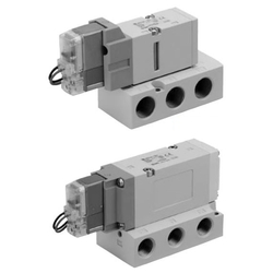
[Features]
・ Built-in full-wave rectifier (For AC)
· The pilot valve features a built-in strainer
・ Base mounted (no VF1000) / single unit
・ Power consumption reduction by power saving circuit
(i)Caution
- Product images may be representative. Refer to the manufacturer's catalog for details.
Part Number
Configured Part Number is shown.
VF5144-5DZ1-03F
5-Port Pilot Type Solenoid Valve VF3000/VF5000 Series, Base Mounted Type, Single Unit Specifications
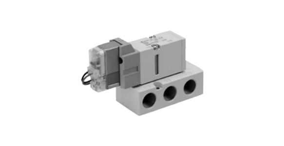
VF3000 Series external appearance
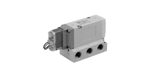
VF5000 Series external appearance
| Model | VF3000 | VF5000 | ||
|---|---|---|---|---|
| Usable Fluids | Air | |||
| Operating Pressure Range MPa | Standard | 2 position single, 3 position | 0.15 to 0.7 | |
| 2-position double | 0.1 to 0.7 | |||
| High-pressure | 2 position single, 3 position | 0.15 to 1.0 | ||
| 2-position double | 0.1 to 1.0 | |||
| Ambient Temperature and Operating Fluid Temperature °C | -10 to 50 (no freezing) | |||
| Maximum Operating Frequency Hz | 2-position single/double | 10 | 5 | |
| 3 Position | 3 | 3 | ||
| Manual Operation | Non-locking, push type Push-turn locking slotted type Push-turn locking hand-operated type | |||
| Pilot Exhaust Method | Individual exhaust main valve / pilot valve common exhaust | Pilot valve: base exhaust type | ||
| Lubrication | Not required | |||
| Mounting Orientation | Free | |||
| Impact Resistance / Vibration Resistance: m/s2 *1: | 300/50 | |||
| Enclosure | Dust-proof (D, Y, T are IP65*2) | |||
*1: Impact resistance: No malfunctions after testing under the following conditions: in the axial direction and at a right angle to the main valve and armature in both energized and non-energized states (once for each condition state). (Initial value)
Vibration resistance: No malfunctions occurred in a 1-sweep test between 45 and 2,000 Hz. The test was performed in both energized and non-energized states and in the axial direction and at right angles to the main valve and armature. (Initial value)
*2: Based on IEC60529. When using with IP65, select the main/pilot valve common exhaust type or pilot valve base exhaust type.
Solenoid Specifications
| Electrical Entry | Grommet (G), (H) L-type plug connector (L) M-type plug connector (M) | DIN terminal (D) DIN (EN175301-803) terminal (Y) Conduit terminal (T) | ||
|---|---|---|---|---|
| G, H, L, M | D, Y, T | |||
| Coil rated voltage (V) | DC | 24, 12 | ||
| AC (50/60 Hz) | 24, 100, 110, 200, 220, 240 | |||
| Allowable Voltage Fluctuation | ±10% of rated voltage * | |||
| Power Consumption W | DC | Standard | 1.5 (with indicator light: 1.55) | 1.5 (with light 1.75) |
| With power saving circuit | 0.55* (only with light) [Inrush 1.55, Holding 0.55] | 0.75* (only with light) [Inrush 1.75, Holding 0.75] | ||
| Apparent power VA * | AC | 24 V | 1.5 (with indicator light: 1.55) | 1.5 (with light 1.75) |
| 100 V | 1.55 (with light 1.65) | 1.55 (with light 1.7) | ||
| 110 V [115 V] | ||||
| 200 V | ||||
| 220 V [230 V] | ||||
| 240 V | ||||
| Surge Voltage Suppressor | Diode (varistor for non-polar type) | |||
| Indicator Light | LED (neon bulb for AC mode of D, Y, T) | |||
- *The 110 V AC and 115 V AC types are interchangeable. The 220 V AC and 230 V AC types are also interchangeable.
- For 115 V AC and 230 V AC, the allowable voltage fluctuation is -15 to +5% of the rated voltage.
- As the S, Z, and T types (with power saving circuit) have voltage drop due to the internal circuits, the allowable voltage fluctuation should be within the range given below.
24 V DC: -7 to +10%
12 V DC: -4% to +10%
Response Time
| Series | Switching Method | Pressure Specification | Operating Pressure Range MPa | Response Time ms (at 0.5 MPa) | ||||
|---|---|---|---|---|---|---|---|---|
| Without indicator light / surge voltage protection circuit | With light and surge voltage suppressor | AC | ||||||
| S, Z Type | R, U Type | |||||||
| VF3000 | 2 Position | Single | Standard Type | 0.15 to 0.7 | 20 | 45 | 23 | 45 |
| Double | 0.1 to 0.7 | 12 | 12 | 12 | 12 | |||
| 3 Position | 0.15 to 0.7 | 30 | 55 | 33 | 55 | |||
| 2 Position | Single | High-pressure type | 0.15 to 1.0 | 23 | 48 | 26 | 48 | |
| Double | 0.1 to 1.0 | 15 | 15 | 15 | 15 | |||
| 3 Position | 0.15 to 1.0 | 33 | 58 | 36 | 58 | |||
| VF5000 | 2 Position | Single | Standard Type | 0.15 to 0.7 | 30 | 55 | 33 | 55 |
| Double | 0.1 to 0.7 | 15 | 15 | 15 | 15 | |||
| 3 Position | 0.15 to 0.7 | 50 | 75 | 53 | 75 | |||
| 2 Position | Single | High-pressure type | 0.15 to 1.0 | 33 | 58 | 36 | 58 | |
| Double | 0.1 to 1.0 | 18 | 18 | 18 | 18 | |||
| 3 Position | 0.15 to 1.0 | 53 | 78 | 56 | 78 | |||
*Based on JIS B8375:1981 dynamic performance testing. (Coil temperature 20°C, at rated voltage)
Structure Drawings / Base Mounted Type
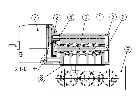
2 position single structure drawing
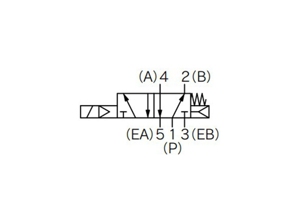
2-position single indicator symbol
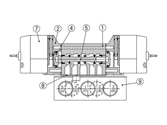
2-position double structure drawing
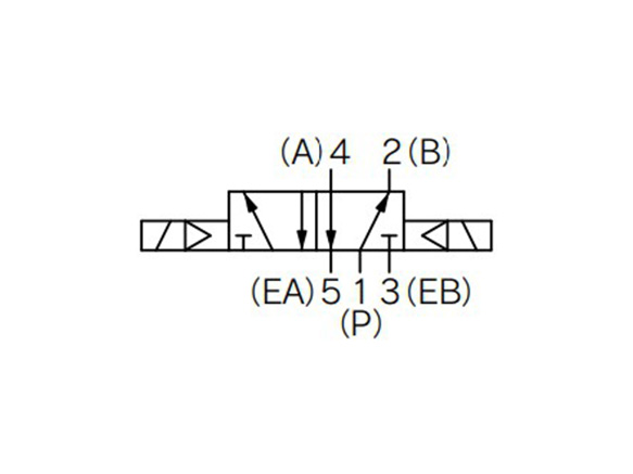
2-position double display symbol
Component Parts
| Number | Part name | Material | Note |
|---|---|---|---|
| 1 | Body | Die-cast aluminum | Urban white |
| 2 | Adapter Plate | Resin | Urban gray |
| 3 | End Plate | Resin | Urban white |
| 4 | Piston | Resin | - |
| 5 | Spool Valve | Aluminum, HNBR | - |
| 6 | Spring | SUS | - |
| Number | Part name | Note |
|---|---|---|
| 7 | Pilot Valve Assembly | Built-in strainer |
| 8 | Gasket | HNBR |
| 9 | Sub-plate | Die-cast aluminum |
| - | Small cross-head/straight-slot combination pan head screw (1 pc.) | For valve mounting |
| - | Hexagon Socket Head Screw (×1) | For valve mounting |
*Valve mount tightening torque M4: 1.4 N⋅m
Drawings / VF3000 Series Base Mounted Type
2-position single
(Unit: mm)
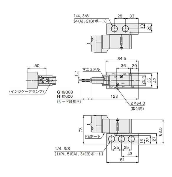
Grommet (G) (H): VF3140-□G/H□□1-02/03□ dimensional drawings
(Unit: mm)
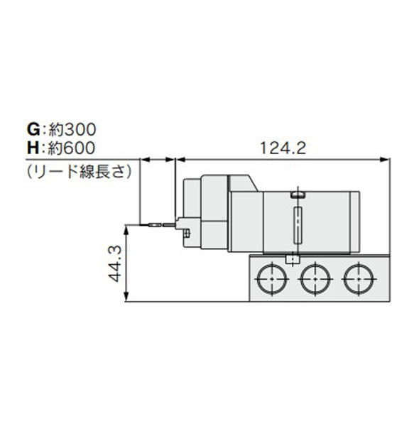
Grommet (G) (H) DC specification without indicator light / surge voltage suppressor dimensional drawing
(Unit: mm)
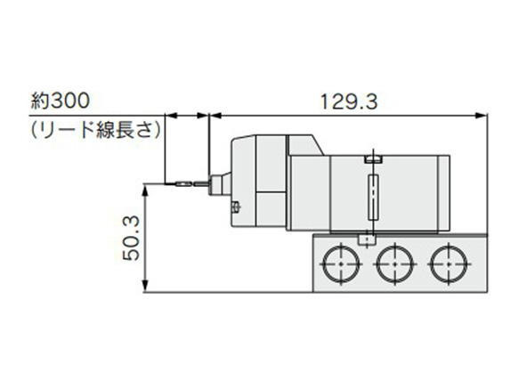
L plug connector (L): VF3140-□L□□1-02/03□ dimensional drawing
*Dimensions same as grommet (G) when not specified.
(Unit: mm)
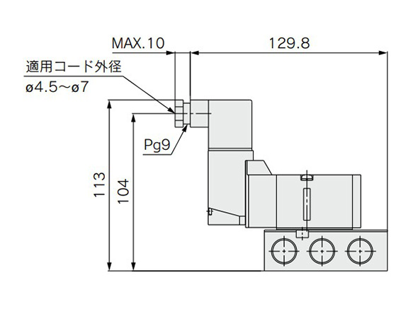
DIN terminal (D) (Y): VF3140-□D/Y□□1-02/03□ dimensional drawing
*Dimensions same as grommet (G) when not specified.
Precautions
- *When using the surge voltage suppressor type, residual voltage will remain. See the manufacturer's catalog for details.
- *See the manufacturer's catalog for information other than the above.
| Part Number |
|---|
| VF5144-5DZ1-03F |
| Part Number | Standard Unit Price | Minimum order quantity | Volume Discount | Days to Ship | Type | Application | Number of Ports | Mounting Orientation | Specifications | Number of Solenoids | Switching Type | Status at Power Off | Voltage | Pipe Port Type | Plumbing Thread Nominal | Applicable Cylinder Dia. (Ø) | Driving Type | CV Value | Seal Type | Pressure Rating (MPa) | Pilot Air Supply | Manual Switch | Coil specifications | Lead wire electrical entry | Manual | Indicator light / Surge voltage suppressor | Made to order specifications | Body options | Valve specifications | Related component type |
|---|---|---|---|---|---|---|---|---|---|---|---|---|---|---|---|---|---|---|---|---|---|---|---|---|---|---|---|---|---|---|
- | 1 Piece(s) | Quote | Solenoid Valves | Single Use | 5-Port Valve | Direct | Standard | [Single] Single | 2-Position Normally Open | Self-Recovery (Spring Return) | DC24V | G | 3/8 | - | Pilot Type Spool | 2.2 | Soft Seal | 0.15 to 0.7 | Internal | Non-Locking | Standard | DIN terminal (with connector) | Non-locking, push type | With indicator light and surge voltage suppressor | - | Pilot valve: base exhaust type | - | - |
Loading...
Basic Information
| Plumbing | Sub-Base Plumbing |
|---|
Please check the type/dimensions/specifications of the part VF5144-5DZ1-03F in the 5-Port Pilot Type Solenoid Valve, Base Mounted, Single Unit VF1000/3000/5000 Series series.
Specification/Dimensions
-
Applicable Cylinder Dia.(Ø)
-
Made to order specifications
-
Valve specifications
- VF3000
- VF5000
-
Related component type
- Sub-plate
-
type
- VF3000
- VF5000
-
Type
- Solenoid Valves
- Related Components
-
Application
- Single Use
- Unit for Manifold Mounting
-
Number of Ports
- 5-Port Valve
-
Mounting Orientation
- Direct
- Manifold Base
-
Specifications
- Standard
- Lubrication Free
-
Number of Solenoids
- Single
- Double
- Single
-
Switching Type
- 2-Position Normally Open
- 2-Position Exhaust
- 3-Position Closed Center
- 3-Position Exhaust Center
- 3-Position Pressure Center
-
Status at Power Off
- Self-Retaining
- Self-Recovery (Spring Return)
-
Voltage
- DC12V
- DC24V
- AC100V
- AC110V
- AC200V
- AC220V
- AC24V
- AC240V
-
Pipe Port Type
- Rc (R)
- NPT
- NPTF
- G
- Rc (R)
-
Plumbing Thread Nominal
-
Driving Type
- Pilot Type Spool
-
CV Value
-
Seal Type
- Soft Seal
-
Pressure Rating(MPa)
- 0.15 to 0.7
- 0.1 to 0.7
- 0.15 to 1
- 0.1 to 1.0
-
Pilot Air Supply
- Internal
-
Manual Switch
- Non-Locking
- Lock
-
Coil specifications
- Standard
- With energy saving circuit (DC only)
-
Lead wire electrical entry
- Grommet (lead wire length: 300 mm)
- L plug connector, lead wire length 300 mm
- M plug connector, lead wire length: 300 mm
- Grommet / Lead wire length: 600 mm
- DIN (EN175301-803) terminal (with connector)
- DIN (EN175301-803) terminal (without connector)
- Conduit terminal
- DIN terminal (with connector)
- DIN terminal (without connector)
- L plug connector (without connector)
- L plug connector (without lead wire)
- M plug connector (without connector)
- M plug connector (without lead wire)
- M plug connector (without lead)
-
Manual
- Non-locking, push type
- Push-turn locking (hand-operated type)
- Push-turn locking (screwdriver-operated type)
-
Indicator light / Surge voltage suppressor
- With indicator light and surge voltage suppressor
- With indicator light and surge voltage suppressor (non-polar)
- With surge voltage suppressor
- With surge voltage suppressor (non-polar)
- Without indicator light / surge voltage suppressor
-
Body options
-
CAD
- 2D
- 3D
Days to Ship
-
- All
- 21 Day(s) or Less
- 32 Day(s) or Less
Specify Alterations
- The specifications and dimensions of some parts may not be fully covered. For exact details, refer to manufacturer catalogs .
Similar Part Numbers
| Part Number |
|---|
| VF3000-71-1T |
| VF3000-71-2 |
| VF3000-71-2F |
| VF5144-5DZ1-03N |
| VF5144-5DZ1-04 |
| VF5144-5DZ1-04F |
| Part Number | Standard Unit Price | Minimum order quantity | Volume Discount | Days to Ship | Type | Application | Number of Ports | Mounting Orientation | Specifications | Number of Solenoids | Switching Type | Status at Power Off | Voltage | Pipe Port Type | Plumbing Thread Nominal | Applicable Cylinder Dia. (Ø) | Driving Type | CV Value | Seal Type | Pressure Rating (MPa) | Pilot Air Supply | Manual Switch | Coil specifications | Lead wire electrical entry | Manual | Indicator light / Surge voltage suppressor | Made to order specifications | Body options | Valve specifications | Related component type |
|---|---|---|---|---|---|---|---|---|---|---|---|---|---|---|---|---|---|---|---|---|---|---|---|---|---|---|---|---|---|---|
- | 1 Piece(s) | Quote | Related Components | - | - | - | - | - | - | - | - | NPTF | 1/4 | - | - | - | - | - | - | - | - | - | - | - | - | - | VF3000 | Sub-plate | ||
- | 1 Piece(s) | Quote | Related Components | - | - | - | - | - | - | - | - | [Rc (R)] Rc | 3/8 | - | - | - | - | - | - | - | - | - | - | - | - | - | VF3000 | Sub-plate | ||
- | 1 Piece(s) | Quote | Related Components | - | - | - | - | - | - | - | - | G | 3/8 | - | - | - | - | - | - | - | - | - | - | - | - | - | VF3000 | Sub-plate | ||
SGD 258.07 | 1 Piece(s) | 32 Day(s) | Solenoid Valves | Single Use | 5-Port Valve | Direct | Standard | [Single] Single | 2-Position Normally Open | Self-Recovery (Spring Return) | DC24V | NPT | 3/8 | - | Pilot Type Spool | 2.2 | Soft Seal | 0.15 to 0.7 | Internal | Non-Locking | Standard | DIN terminal (with connector) | Non-locking, push type | With indicator light and surge voltage suppressor | - | Pilot valve: base exhaust type | - | - | ||
SGD 258.07 | 1 Piece(s) | 32 Day(s) | Solenoid Valves | Single Use | 5-Port Valve | Direct | Standard | [Single] Single | 2-Position Normally Open | Self-Recovery (Spring Return) | DC24V | [Rc (R)] Rc | 1/2 | 200 or less | Pilot Type Spool | 2.7 | Soft Seal | 0.15 to 0.7 | Internal | Non-Locking | Standard | DIN terminal (with connector) | Non-locking, push type | With indicator light and surge voltage suppressor | - | Pilot valve: base exhaust type | - | - | ||
SGD 258.07 | 1 Piece(s) | 32 Day(s) | Solenoid Valves | Single Use | 5-Port Valve | Direct | Standard | [Single] Single | 2-Position Normally Open | Self-Recovery (Spring Return) | DC24V | G | 1/2 | 200 or less | Pilot Type Spool | 2.7 | Soft Seal | 0.15 to 0.7 | Internal | Non-Locking | Standard | DIN terminal (with connector) | Non-locking, push type | With indicator light and surge voltage suppressor | - | Pilot valve: base exhaust type | - | - |


How can we improve?
How can we improve?