(!)Due to Microsoft's end of support for Internet Explorer 11 on 15/06/2022, this site does not support the recommended environment.
Instead, please kindly use other browsers like Google Chrome, Microsoft Edge or Mozilla Firefox.
50,000 Stock items for Same Day Ship Out.
All Categories
Categories
- Automation Components
A wide variety of standard and configurable components for factory automation engineers in industries such as automotive, semiconductor, packaging, medical and many more.
- Linear Motion
- Rotary Motion
- Connecting Parts
- Rotary Power Transmission
- Motors
- Conveyors & Material Handling
- Locating, Positioning, Jigs & Fixtures
- Inspection
- Sensors, Switches
- Pneumatics, Hydraulics
- Vacuum Components
- Hydraulic Equipment
- Discharging / Painting Devices
- Pipe, Tubes, Hoses & Fittings
- Modules, Units
- Heaters, Temperature Control
- Framing & Support
- Casters, Leveling Mounts, Posts
- Doors, Cabinet Hardware
- Springs, Shock Absorbers
- Adjusting, Fastening, Magnets
- Antivibration, Soundproofing Materials, Safety Products
- Fasteners
A good selection of accessories such as screws, bolts, washers and nuts that you may need for your daily engineering usage.
- Materials
Browse industrial materials ranging from heat insulating plates, sponges, to metal and plastic materials in different sizes to meet your various applications.
- Wiring Components
A wide variety of wiring parts for connecting and protecting control and PC parts including Connectors, Cables, Electric Wires, Crimping Terminals and more.
- LAN Cables / Industrial Network Cables
- Cables by Application
- Cables with Connectors
- RS232 / Personal Computers / AV Cables
- Wires/Cables
- Connectors (General Purpose)
- Crimp Terminals
- Zip Ties
- Cable Glands
- Cable Bushings/Clips/Stickers
- Screws/Spacers
- Cable Accessories
- Tubes
- Protection Tubes
- Ducts/Wiremolds
- General Purpose Tools
- Dedicated Tools
- Soldering Supplies
- Electrical & Controls
A wide variety of controls and PC parts for electrical engineers including Controls, Powers, PC parts and more.
- Cutting Tools
A wide variety of cutting tools for many uses and work materials including End Mills, Drills, Cutters, Reamers, Turning Tools and more.
- Carbide End Mills
- HSS End Mills
- Milling Cutter Inserts/Holders
- Customized Straight Blade End Mills
- Dedicated Cutters
- Turning Tools
- Drill Bits
- Screw-Hole-Related Tools
- Reamers
- Chamfering / Centering Tools
- Fixtures Related to Cutting Tools
- Step Drills
- Hole Saws
- Clean Key Cutters
- Core Drills (Tip Tools)
- Magnetic Drilling Machine Cutters
- Drill Bits for Electric Drilling Machines
- Woodworking Drill Cutters
- Drills for Concrete
- Processing Tools
A wide variety of tools and supplies used in processing including Machine Tools, Measurement Tools, Grinding and Polishing Supplies and more.
- Material Handling & Storage
A wide variety of goods used in shipment, material handling and warehouse including Tape supplies, Stretch film, Truck, Shelf, Crane and more.
- Tape Supplies
- Cushioning Materials
- Stretch Films
- Cardboard
- Plastic Bags
- PP Bands
- Magic Tapes / Tying Belts
- Rubber Bands
- Strings/Ropes
- Cable Ties
- Tags
- Labelers
- Unpacking Cutters
- Packing Support Equipment
- Cloth Sheets for Packing
- Conveyance/Dolly Carts
- Tool Wagons
- Tool Cabinets / Container Racks
- Lifters / Hand Pallets
- Container Pallets
- Storage Supplies
- Shelves/Racks
- Work Benches
- Suspended Clamps/Suspended Belts
- Jack Winches
- Chain Block Cranes
- Bottles/Containers
- Bicycle Storage Area
- Safety & General Supplies
A large variety of goods for every kind of factories and offices including Protection items, Cleaning supplies, sanitations, office supplies and more.
- Lab & Clean Room Supplies
A large variety of items used in R&D and Clean Room including research Equipment, Laboratory Essentials, Analysis Supplies, Clean Environment-Related Equipment and more.
- Press Die Components
Choose from thousands of standard stamping die components including Punch & Die, Gas Springs, Guide Components, Coil Springs and many more.
- Plastic Mold Components
Browse our wide variety of mold components including Ejector Pins, Sleeves, Leader Components, Sprue Bushings and many more.
- Ejector Pins
- Sleeves, Center Pins
- Core Pins
- Sprue bushings, Gates, and other components
- Date Mark Inserts, Recycle Mark Inserts, Pins with Gas Vent
- Undercut, Plates
- Leader Components, Components for Ejector Space
- Mold Opening Controllers
- Cooling or Heating Components
- Accessories, Others
- Components of Large Mold, Die Casting
- Injection Molding Components
Browse our injection molding components including Heating Items, Couplers, Hoses and more.
- Injection Molding Machine Products
- Accessories of Equipment
- Auxiliary Equipment
- Air Nippers
- Air Cylinders
- Air Chuck for Runner
- Chuck Board Components
- Frames
- Suction Components
- Parallel Air Chuck
- Special Air Chuck
- Chemical for Injection Molding
- Mold Maintenance
- Heating Items
- Heat Insulation Sheets
- Couplers, Plugs, One-touch Joints
- Tubes, Hoses, Peripheral Components
Search by Application
Brands
- Scheduled Maintenance Notice: This site will be unavailable due to scheduled maintenance from 9:00 24/11/2024 to 7:00 (SGT) 25/11/2024. We apologize for the inconvenience.
- Notice of End of Sales for Economy Series Pneumatic Equipment Category. More information.
Electric Gripper, 2-Finger Type, LEHF Series (LEHF20K2-24-S1MJ)
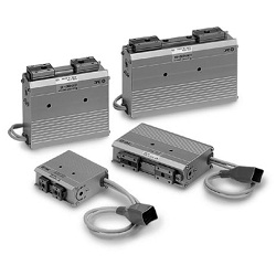
Electric gripper for a variety of workpieces with a long stroke.
[Features]
· Step motor (servo 24 V DC).
· Easy to complete setup with 2 items, namely, position and thrust.
· Controllers are shipped with the setup for actuator specifications (the actuator and controller are sold as a package).
· With drop prevention function.
· Self-lock mechanism reduces power consumption.
· With gripping check function.
· Possible to set position, speed and force (64 points).
*Values inside parentheses () are for long stroke.
(i)Caution
- Product images are representative images. CAD data is not supported for some model numbers.
Part Number
Configured Part Number is shown.
LEHF20K2-24-S1MJ
LEHF Series 2-Finger Type Electric Gripper Specifications
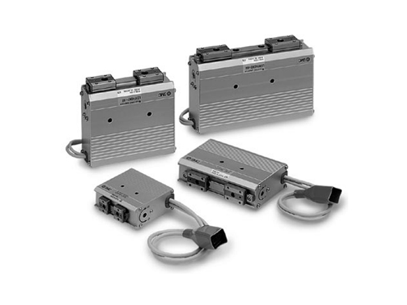
LEHF Series 2-Finger Type Electric Gripper external appearance
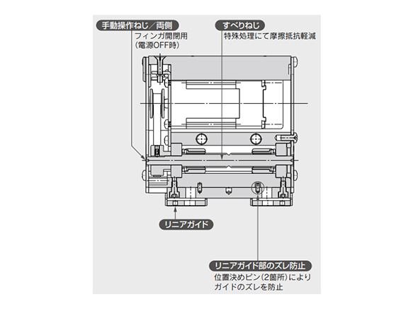
Features of LEHF Series 2-Finger Type Electric Gripper
Specifications
| Model | LEHF10 | LEHF20 | LEHF32 | LEHF40 | ||
|---|---|---|---|---|---|---|
| Actuator specifications | Open and close stroke / both sides (mm) | Basic | 16 | 24 | 32 | 40 |
| Long stroke | 32 | 48 | 64 | 80 | ||
| Lead (mm) | 40/15 (2.667) | 50/15 (3.333) | 70/16 (4.375) | 70/16 (4.375) | ||
| Gripping force (N)*1 *3 | 3 to 7 | 11 to 28 | 48 to 120 | 72 to 180 | ||
| Open and close speed / pushing speed (mm/s)*2 *3 | 5 to 80 / 5 to 20 | 5 to 100 / 5 to 30 | ||||
| Actuation type | Slide screw + belt | |||||
| Finger guide type | Linear guide (no circulation) | |||||
| Repeated length measurement accuracy (mm)*4 | ±0.05 | |||||
| Finger backlash / one side (mm)*5 | 0.5 or less | |||||
| Repeatability (mm)*6 | ±0.05 | |||||
| Positioning repeatability / one side (mm) | ±0.1 | |||||
| Lost motion / one side (mm)*7 | 0.3 or less | |||||
| Impact/vibration resistance (m/s2)*8 | 150/30 | |||||
| Max. operating frequency (C.P.M) | 60 | |||||
| Operating temp. range (°C) | 5 to 40 | |||||
| Operating humidity range (%RH) | 90 or less (no condensation) | |||||
| Weight (g) | Basic | 340 | 610 | 1,625 | 1,980 | |
| Long stroke | 370 | 750 | 1,970 | 2,500 | ||
| Electric specifications | Motor size | □20 | □28 | □42 | ||
| Motor type | Step motor (servo 24 V DC) | |||||
| Encoder | Incremental A/B phase (800 pulse/rotation) | |||||
| Rated voltage (V) | 24 V DC ±10% | |||||
| Power consumption / standby power consumption when operating (W)*9 | 11/7 | 28/15 | 34/13 | 36/13 | ||
| Max. instantaneous power consumption (W)*10 | 19 | 51 | 57 | 61 | ||
*1 Gripping force should be from 10 to 20 times the workpiece weight. Moving force should be 150% when releasing the workpiece. Gripping force accuracy should be: LEHF10: ±30% (F.S.), LEHF20: ±25% (F.S.), LEHF32/LEHF40: ±20% (F.S.). Gripping the workpiece with a heavy attachment and fast pushing speed may not satisfy the product specifications. In this case, decrease the weight and lower the pushing speed.
*2 Pushing speed should be set within the range during pushing (gripping) operation. Otherwise, it may cause malfunction. The open/close speed and pushing speed are for both fingers. The speed for one finger is 1/2 this value.
*3 The speed and force may change depending on the cable length, load, mounting conditions, etc. Furthermore, if the cable length exceeds 5 m, then the speed and force will decrease by up to 10% for each 5 m. (At 15 m: reduced by up to 20%)
*4 Repeated length measurement accuracy means dispersion (value on the controller monitor) when the workpiece is repeatedly held in the same position.
*5 There is no effect on the backlash during pushing (gripping). Make the stroke longer by the amount of backlash when opening.
*6 Repeatability means the variation of the gripping position (workpiece position) when the gripping operation is repeatedly performed in the same sequence for the same workpiece.
*7 A reference value for correcting an error in reciprocal operation which occurs during the positioning operation.
*8 Impact resistance: No malfunction occurred when the slide table was tested with a drop tester in both an axial direction and a perpendicular direction to the lead screw. (Test was performed with the gripper in the initial state.) Vibration resistance: No malfunction occurred in a test ranging from 45 to 2,000 Hz. Test was performed in both an axial direction and a perpendicular direction to the lead screw. (Test was performed with the actuator in the initial state.)
*9 The power consumption (including the controller) is for when the actuator is operating. The standby power consumption when operating is for when the gripper is stopped in the set position during operation (including energy-saving mode when gripping).
*10 The maximum instantaneous power consumption (including the controller) is for when the actuator is operating. This value can be used for the selection of the power supply.
External dimensional drawing
(Unit: mm)
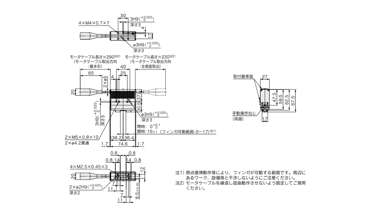
LEHF10K2-16 / basic dimensional drawing
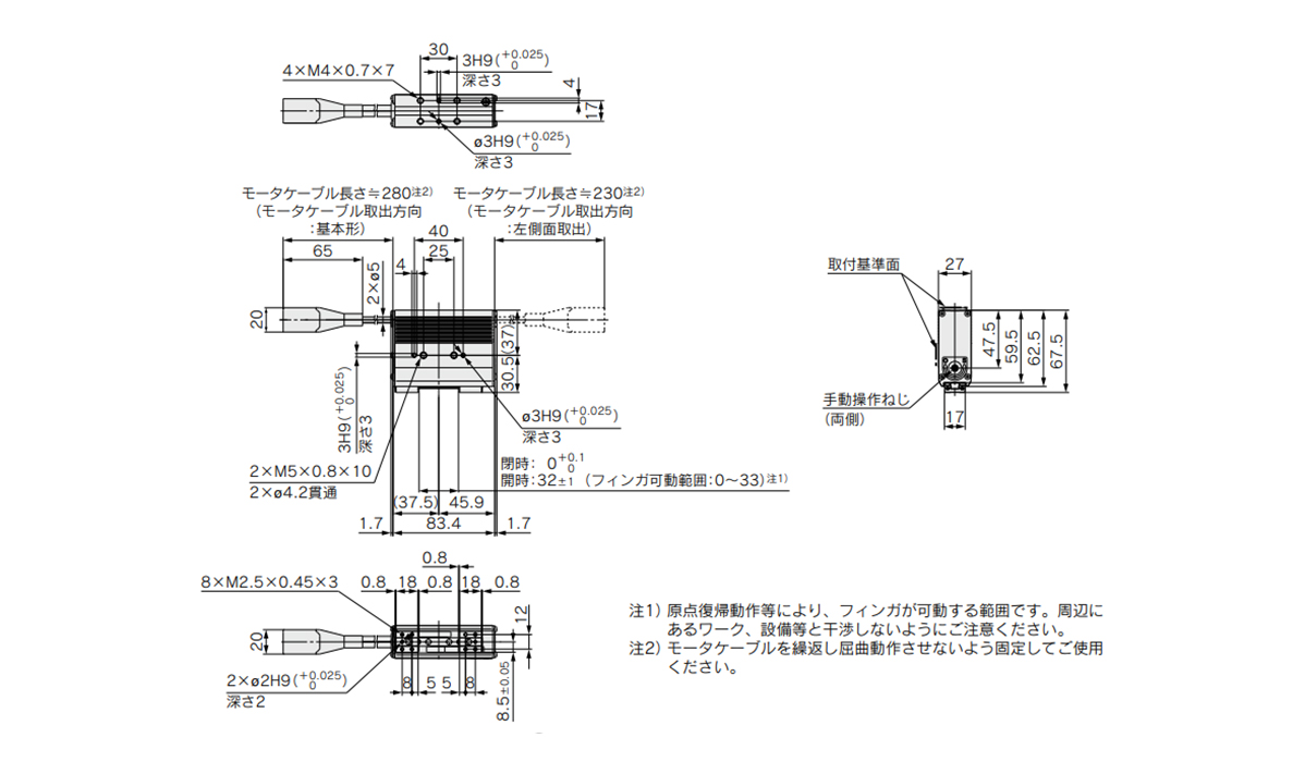
LEHF10K2-32 / long stroke dimensional drawing
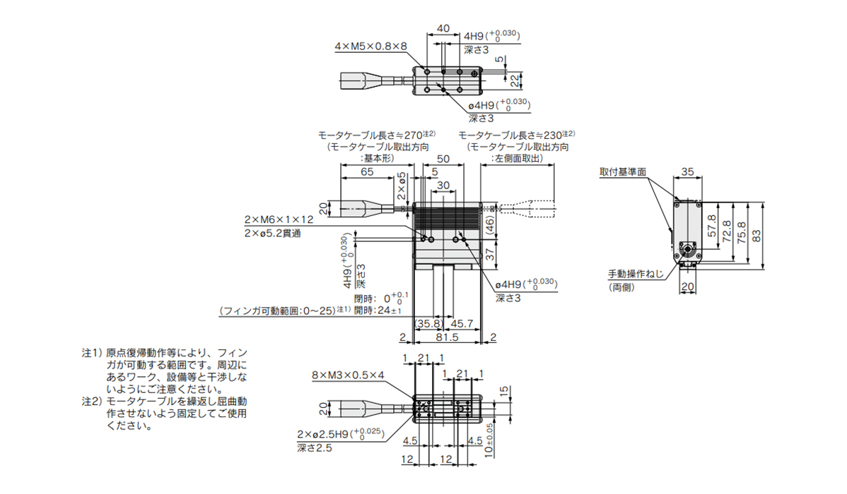
LEHF20K2-24 / basic dimensional drawing
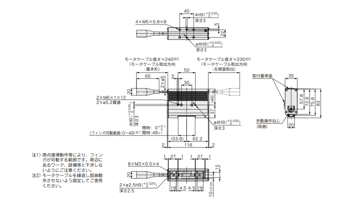
LEHF20K2-48 / long stroke dimensional drawing
Common Cautions
*1 Range within which the finger can move when it returns to origin. Make sure the workpiece mounted on the finger does not interfere with the workpieces and equipment around the finger.
*2 Secure the motor cable so that it will not be bent repeatedly.
Structure drawing
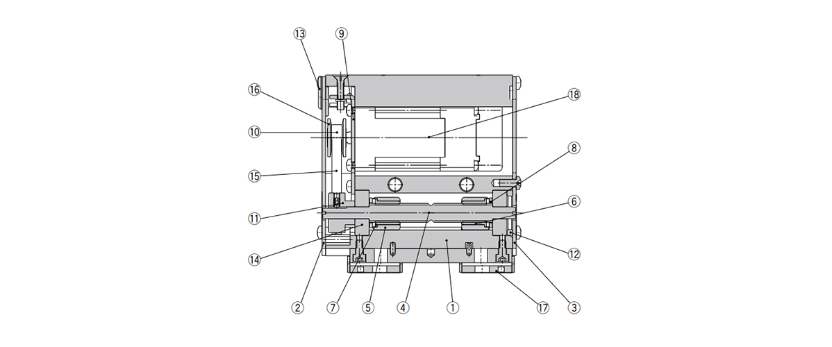
LEHF Series structure drawing
| No. | Description | Material | Note |
|---|---|---|---|
| 1 | Body | Aluminum alloy | Anodized |
| 2 | Side plate A | Aluminum alloy | Anodized |
| 3 | Side plate B | Aluminum alloy | Anodized |
| 4 | Slide shaft | Stainless steel | Heat treated + Specially treated |
| 5 | Slide bushing | Stainless steel | - |
| 6 | Slide nut | Stainless steel | Heat treated + Specially treated |
| 7 | Slide nut | Stainless steel | Heat treated + Specially treated |
| 8 | Fixed plate | Stainless steel | - |
| 9 | Motor plate | Carbon steel | - |
| 10 | Pulley A | Aluminum alloy | - |
| 11 | Pulley B | Aluminum alloy | - |
| 12 | Bearing stopper | Aluminum alloy | - |
| 13 | Rubber bushing | NBR | - |
| 14 | Bearing | - | - |
| 15 | Belt | - | - |
| 16 | Flange | - | - |
| 17 | Finger assembly | - | - |
| 18 | Step motor (servo 24 V DC) | - | - |
Mounting Method
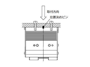
When using the thread on the body
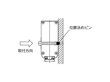
When using the thread on the mounting plate
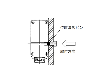
When using the thread on the back of the body
Precautions
- *The parameters of the stroke and the open/close speed are for both fingers.
- *The stroke and the open/close speed for one finger is 1/2 the set parameter.
- *When gripping a workpiece by the product, be sure to set to "Pushing."
- *Also, do not hit the workpiece with the finger and attachment during positioning or in the range of positioning. Otherwise, the lead screw can get caught and this may result in a malfunction. However, if the workpiece cannot be gripped when pushing (such as if the workpiece is a plastically deformed workpiece or rubber component, etc.), grip it when positioning giving consideration to the elastic force of the workpiece.
- *There is no effect on the backlash during pushing.
- *The return to origin is done by pushing. The finger position can be displaced by the effect of the backlash during positioning. This backlash displacement should be considered when setting the position.
- *See the manufacturer's catalog for product information other than the above.
- *Product images are representative images.
| Part Number |
|---|
| LEHF20K2-24-S1MJ |
| Part Number | Standard Unit Price | Minimum order quantity | Volume Discount | Days to Ship | Dimensions when open (mm) | Maximum Gripping Force (Opening Side, Electric Type) (N) | Maximum Gripping Force (Closing Side, Electric Type) (N) | Size | Stroke (mm) | Motor cable entry direction | Actuator cable type | Actuator cable length | Controller / driver type | I/O cable length | Controller/driver mounting method | Communications plug |
|---|---|---|---|---|---|---|---|---|---|---|---|---|---|---|---|---|
- | 1 Piece(s) | Quote | 24 | 28 | 28 | 20 | 24 | Entry on the right side | Standard cable | 1.5 m | CC-Link direct input type | None | Screw mounting | None |
Loading...
Basic Information
| Type | Main Body(Electric Type) | Gripping Methods | Pinch, Parallel Type / Open, Parallel Type | Number of Fingers | 2 pcs. |
|---|---|---|---|---|---|
| Main Body Shape | Lateral Shape | Dimensions when closed(mm) | 0 | Environment, Applications | Standard |
| Additional Functions | With Linear Guide | Stroke Adjustment Mechanism | Open/Close Dual Adjustment |
Please check the type/dimensions/specifications of the part LEHF20K2-24-S1MJ in the Electric Gripper, 2-Finger Type, LEHF Series series.
Specification/Dimensions
-
type
- LEHF10
- LEHF20
- LEHF32
- LEHF40
-
Dimensions when open(mm)
-
Maximum Gripping Force (Opening Side, Electric Type)(N)
-
Maximum Gripping Force (Closing Side, Electric Type)(N)
-
Size
- 10
- 20
- 32
- 40
-
Stroke(mm)
-
Motor cable entry direction
- Entry on the left side
- Entry on the right side
-
Actuator cable type
- None
- Robot cable
- Standard cable
-
Actuator cable length
- 1.5 m
- 3 m
- 5 m
- 8 m
- 10 m
- 15 m
- 20 m
- None
-
Controller / driver type
- CC-Link direct input type
- NPN programless type
- NPN pulse input type
- NPN step data input type
- None
- PNP programless type
- PNP pulse input type
- PNP step data input type
-
I/O cable length
- 1.5 m
- 3 m
- 5 m
- None
-
Controller/driver mounting method
- DIN rail mounting
- Screw mounting
-
Communications plug
- None
- Straight-type communication plug connector
- T-branch-type communication plug connector
-
CAD
- 2D
- 3D
Days to Ship
-
- All
- 21 Day(s) or Less
- 32 Day(s) or Less
Specify Alterations
- The specifications and dimensions of some parts may not be fully covered. For exact details, refer to manufacturer catalogs .
Similar Part Numbers
| Part Number |
|---|
| LEHF10K2-16-6PD |
| LEHF10K2-16-AN1 |
| LEHF10K2-16-R1 |
| LEHF20K2-24-S1MJS |
| LEHF20K2-24-S1MJT |
| LEHF20K2-24-S1MJTD |
| Part Number | Standard Unit Price | Minimum order quantity | Volume Discount | Days to Ship | Dimensions when open (mm) | Maximum Gripping Force (Opening Side, Electric Type) (N) | Maximum Gripping Force (Closing Side, Electric Type) (N) | Size | Stroke (mm) | Motor cable entry direction | Actuator cable type | Actuator cable length | Controller / driver type | I/O cable length | Controller/driver mounting method | Communications plug |
|---|---|---|---|---|---|---|---|---|---|---|---|---|---|---|---|---|
- | 1 Piece(s) | Quote | 16 | 7 | 7 | 10 | 16 | Entry on the right side | None | None | PNP step data input type | None | DIN rail mounting | None | ||
- | 1 Piece(s) | Quote | 16 | 7 | 7 | 10 | 16 | Entry on the right side | None | None | NPN pulse input type | 1.5 m | Screw mounting | None | ||
- | 1 Piece(s) | Quote | 16 | 7 | 7 | 10 | 16 | Entry on the right side | Robot cable | None | None | 1.5 m | Screw mounting | None | ||
- | 1 Piece(s) | Quote | 24 | 28 | 28 | 20 | 24 | Entry on the right side | Standard cable | 1.5 m | CC-Link direct input type | None | Screw mounting | Straight-type communication plug connector | ||
- | 1 Piece(s) | Quote | 24 | 28 | 28 | 20 | 24 | Entry on the right side | Standard cable | 1.5 m | CC-Link direct input type | None | Screw mounting | T-branch-type communication plug connector | ||
- | 1 Piece(s) | Quote | 24 | 28 | 28 | 20 | 24 | Entry on the right side | Standard cable | 1.5 m | CC-Link direct input type | None | DIN rail mounting | T-branch-type communication plug connector |
Tech Support
- Factory Automation, Electronics, Tools, & MRO (Maintenance, Repair and Operations)
- Tel:(65) 6733 7211 / FAX:(65) 6733 0211
- 9:00am - 6:00pm (Monday - Friday)
- Technical Inquiry


How can we improve?
How can we improve?